Tiancheng Zhixian (Shenzhen) Technology Co., Ltd.
News

How Can a USB-RTD High-Speed Programmer for LCD Driver Boards Improve Firmware Programming Efficiency

2026-10-10 0 Leave me a message

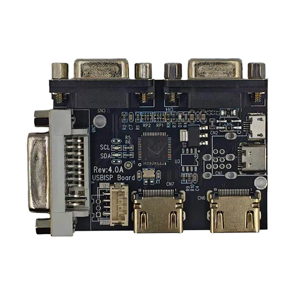
SKY-TDM provides the USB-RTD High-Speed Programmer for LCD Driver Board applications, helping display manufacturers and engineering teams simplify firmware programming, controller debugging, and production-line updates for compatible Realtek RTD display controller ICs. Its flexible interfaces support development, testing, and manufacturing workflows.

Reliable firmware programming is essential for consistent LCD performance, efficient manufacturing, and long-term product maintenance. A dedicated USB-RTD programmer offers a practical way to write and update firmware on compatible Realtek RTD-based LCD driver boards. With USB connectivity, multiple programming interfaces, and support for engineering and production workflows, it helps reduce repetitive manual operations and simplify controller-board integration. This guide explains its working principles, key features, technical specifications, applications, selection criteria, and practical considerations for manufacturers seeking a more efficient LCD firmware programming solution.

USB-RTD High-Speed Programmer for LCD Driver Board

Table of Contents

  1. What Is a USB-RTD High-Speed Programmer?
  2. Why Does Firmware Programming Matter?
  3. Key Features and Technical Advantages
  4. Technical Specifications at a Glance
  5. How Does the Programming Workflow Work?
  6. Industrial Applications and Use Cases
  7. How to Choose the Right Programmer
  8. Practical Tips for Reliable Programming
  9. Frequently Asked Questions
  10. Conclusion and Next Steps

1. What Is a USB-RTD High-Speed Programmer?

A USB-RTD High-Speed Programmer for LCD Driver Board systems is a specialized hardware tool used to program or update firmware on compatible Realtek RTD series display controller integrated circuits. It provides a connection between a computer and a target controller board, enabling engineers to perform firmware-related tasks during development, manufacturing, testing, and maintenance.

LCD driver boards coordinate communication between display panels and their host systems. Depending on the controller design and firmware configuration, they can manage display timing, resolution settings, input signal processing, and other display-related functions. Correct firmware is therefore essential for achieving the intended behavior of a customized LCD solution.

Unlike a general-purpose programming tool, an RTD-focused programmer is designed around the requirements of supported Realtek display controller platforms. It can help manufacturers standardize programming procedures across compatible boards and reduce the complexity of repeated firmware operations.

For more information about compatible hardware, explore SKY-TDM's USB-RTD programmer product page.


2. Why Does Firmware Programming Matter?

Firmware is a critical part of an LCD controller's operation. Even when the hardware is assembled correctly, an unsuitable firmware version or an incomplete programming process can prevent a display from operating as intended.

Manufacturers often need to program controller boards repeatedly as products move from engineering samples to pilot runs and full-scale production. A dedicated programming solution helps establish a more consistent process.

Improving Production Efficiency

Manual programming methods can involve repeated connections, separate tools, and additional operator checks. A dedicated programmer can simplify these steps, making it easier to establish standardized programming stations and repeatable procedures.

Maintaining Firmware Consistency

Using an approved firmware file and a documented programming procedure helps reduce variation between boards. This is particularly important when manufacturing multiple units for the same display model or maintaining several product versions.

Supporting Product Development

During research and development, engineers may need to test different panel configurations, display resolutions, or timing parameters. Efficient firmware programming helps shorten the time between design changes and validation tests.

Simplifying Maintenance

When a compatible display product requires a firmware update, a dedicated programmer can provide a controlled way to perform the update, subject to the target board's design and firmware requirements.


3. Key Features and Technical Advantages

Dedicated Support for Realtek RTD Controllers

The programmer is intended for compatible Realtek RTD series display controller ICs. The product family's published compatibility information includes controller models such as RTD2785, RTD2555T, RTD2483, RTD2270, RTD2271, RTD2660, RTD2660H, RTD2556, RTD2795, and RTD2995. Actual compatibility should be confirmed for the specific controller board and firmware configuration before purchase.

Multiple Connection Interfaces

Different LCD controller boards use different layouts and programming connections. The programmer provides several interface options to accommodate supported board configurations.

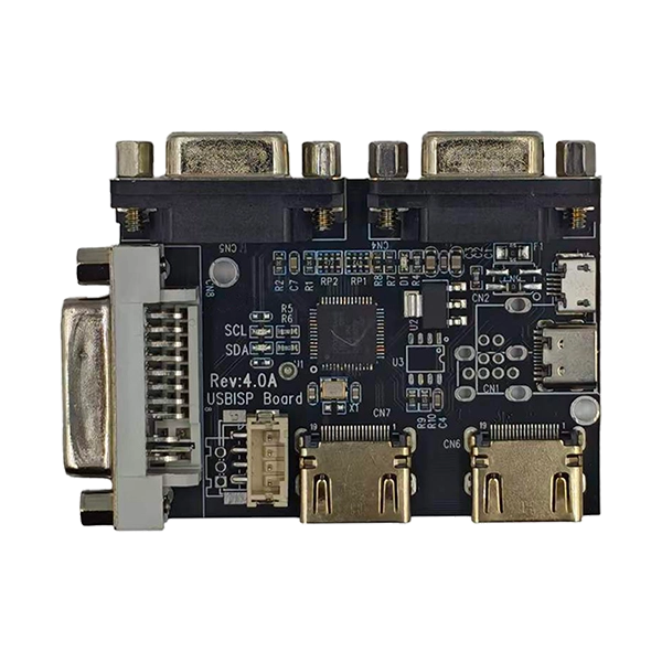
  • HDMI interfaces: Two HDMI connections are listed for supported programming or signal-input configurations.
  • VGA interfaces: Two VGA connections provide additional connection options.
  • DVI interface: A DVI connection supports compatible board configurations.
  • USB Type-C and Micro USB: USB connectivity supports connection to a host computer.
  • PH2.0 programming connector: A dedicated connector supports compatible programming-header configurations.

These options can help engineers work with different supported controller-board designs without relying on a separate programming tool for every configuration.

Designed for Development and Production

A programming tool should support more than one stage of the product lifecycle. This solution can be used during prototype development, firmware verification, production programming, and maintenance activities for compatible LCD driver boards.

Compact Hardware and Visual Indicators

The product information describes a compact design with LED indicators for power, SCL, and SDA status. These indicators can help operators check basic connection or communication conditions during setup and troubleshooting. They should be used alongside the applicable operating instructions rather than treated as a substitute for complete firmware verification.

Industrial Operating Conditions

The published product specifications list an operating temperature range of -30°C to +80°C and a USB power input range of approximately 4.5–5.5 V. Correct power supply, secure connections, suitable cable routing, and appropriate interference control remain important for reliable operation.


4. Technical Specifications at a Glance

The following table summarizes the main published characteristics of the USB-RTD programmer. Buyers should confirm the final configuration and compatibility requirements with the supplier before integrating it into a production process.

Specification Published Details Practical Significance
Product Type USB-RTD High-Speed Programmer for LCD Driver Board Dedicated firmware programming solution
Supported Controller Family Realtek RTD series For compatible RTD-based display controller boards
USB Connectivity USB Type-C, USB 2.0, Micro USB Provides host-computer connection options
Programming Interfaces 2 × VGA, 2 × HDMI, 1 × DVI, PH2.0 header Accommodates different supported board configurations
Input Voltage Approximately 4.5–5.5 V Requires a suitable USB power source
Operating Temperature -30°C to +80°C Published operating range for applicable conditions
Status Indicators Power, SCL, and SDA LEDs Supports basic visual status checks
Primary Applications Programming, testing, maintenance, and R&D Supports multiple stages of the product lifecycle

For related display hardware, see SKY-TDM's LCD display and touchscreen solutions and its range of LCD driver boards.


5. How Does the Programming Workflow Work?

A well-defined programming workflow helps reduce avoidable errors and makes firmware operations easier to repeat. The exact software, file format, and connection procedure depend on the controller board and the manufacturer's instructions.

Step 1: Confirm Hardware Compatibility

Identify the controller IC model, board revision, target LCD panel, and required firmware version. Check that the programmer and the selected interface are suitable for the board before making any connections.

Step 2: Connect the Programmer

Connect the programmer to the host computer using a supported USB connection. Connect the target LCD controller board through the appropriate supported programming interface or header. Verify pin assignments and grounding requirements before powering the system.

Step 3: Prepare the Firmware

Obtain the correct firmware file for the intended controller and panel configuration. Keep approved firmware versions organized by product model and revision. Using an unrelated or unverified file can cause display malfunction or prevent the board from operating correctly.

Step 4: Perform the Programming Operation

Launch the applicable programming software and follow the prescribed procedure to write the firmware. Monitor the available status indicators and software messages throughout the process. Avoid disconnecting the USB cable or interrupting power while programming is in progress.

Step 5: Verify and Test the Board

After programming, confirm that the operation has completed successfully using the available verification method. Test the controller board with the intended LCD panel and signal source. Check the expected resolution, timing behavior, image stability, and relevant product functions.

Step 6: Record Production Results

For manufacturing environments, record the firmware version, controller-board revision, programming result, and any rework required. A traceable record helps engineers investigate defects and maintain consistency between production batches.


6. Industrial Applications and Use Cases

The USB-RTD programmer is relevant to businesses that develop, manufacture, integrate, or maintain LCD products based on compatible Realtek RTD controllers.

  • Industrial LCD manufacturing: Program compatible controller boards before final display assembly.
  • Custom monitor production: Load the appropriate firmware for supported display configurations.
  • Engineering laboratories: Support firmware development, debugging, and controller-board verification.
  • Medical display equipment: Assist with programming compatible display controllers used in equipment development and production, subject to the product's regulatory and validation requirements.
  • OEM display integration: Prepare controller boards for integration into customer-specific equipment.
  • Maintenance and after-sales service: Update firmware on compatible products when an approved update is available.
  • Production-line quality control: Incorporate programming and verification steps into documented manufacturing procedures.

For example, an industrial monitor manufacturer may need to configure several controller-board batches for different LCD panel models. By confirming compatibility and using the correct firmware for each configuration, the engineering team can establish a repeatable programming procedure and reduce the risk of mixing firmware versions during assembly.

This is an illustrative workflow, not a claim about a specific customer deployment or measured production result. Actual performance depends on the board, firmware, computer, software, and operating procedure.


7. How to Choose the Right Programmer

Selecting a programming tool requires more than comparing interface counts or advertised speed. The most important consideration is whether the tool works with the exact controller and production process.

Check the Controller IC

Confirm the exact RTD controller model and board revision. Membership in the Realtek RTD family alone does not guarantee compatibility with every programmer or firmware package.

Evaluate Connection Requirements

Review the available board connectors, programming headers, and required USB connection. Choose a configuration that fits the actual hardware layout and the intended working environment.

Consider Production Volume

Engineering teams may prioritize flexibility for testing different firmware versions, while production teams may prioritize repeatability, operator training, and traceable programming results. Estimate the number of boards processed per shift before planning programming stations.

Review Software and Technical Support

Ask whether the required software, firmware guidance, operating instructions, and compatibility assistance are available for the target project. These factors can be just as important as hardware specifications during integration.

Compare the Total Workflow Cost

Consider the time required for connection, programming, verification, operator handling, and rework. A tool that fits the existing process and reduces unnecessary steps may provide greater practical value than a solution selected on headline speed alone.


8. Practical Tips for Reliable Programming

Good operating practices help protect the programmer and target board while supporting consistent results.

  • Use the correct power input: Follow the manufacturer's specified voltage range and avoid applying an unsupported supply.
  • Check the pinout: Verify the programming header and signal connections before connecting the hardware.
  • Keep cables secure: Use short, suitable cables where practical and avoid loose connections.
  • Control electromagnetic interference: Arrange cables and equipment to minimize interference in electrically noisy environments.
  • Use approved firmware: Confirm that the firmware matches the target controller, panel, and board revision.
  • Avoid interruptions: Do not disconnect the programmer or interrupt power during a write operation unless the operating procedure explicitly allows it.
  • Investigate failed operations: Check the connection, power, firmware selection, and software configuration before attempting another programming cycle.
  • Document each production batch: Maintain records of firmware revisions, test results, and corrective actions.

If a programming operation fails repeatedly, stop and verify the hardware and software configuration rather than repeatedly retrying an unknown setup. Consult the supplier for model-specific troubleshooting instructions when necessary.


9. Frequently Asked Questions

Q1: What is the USB-RTD High-Speed Programmer for LCD Driver Board used for?

It is designed to program and update firmware on compatible Realtek RTD series display controller ICs. Typical uses include engineering development, controller-board production, testing, and maintenance.

Q2: Which controller ICs are supported?

The published compatibility list includes models such as RTD2785, RTD2555T, RTD2483, RTD2270, RTD2271, RTD2660, RTD2660H, RTD2556, RTD2795, and RTD2995. Confirm support for your exact board revision and firmware requirements before ordering.

Q3: Which interfaces are available?

The product information lists two VGA interfaces, two HDMI interfaces, one DVI interface, and a PH2.0 programming header, along with USB Type-C, USB 2.0, and Micro USB connectivity. The appropriate connection depends on the target board configuration.

Q4: Can this programmer be used in mass production?

Yes. It is intended for development and production workflows involving compatible RTD-based LCD controller boards. For high-volume use, evaluate programming time, verification procedures, operator handling, and the number of stations needed to meet production targets.

Q5: Can it support firmware updates after a product has been shipped?

It can be used for maintenance or firmware updates when the target controller board supports the required programming procedure. Confirm the approved firmware and update method before performing field maintenance.

Q6: Is it compatible with every LCD driver board?

No. It is designed for supported Realtek RTD series display controller ICs and compatible board configurations. Other controller families and unsupported board designs should not be assumed to work with this programmer.

Q7: What should buyers provide when requesting a quotation?

Provide the controller IC model, board revision, LCD panel model, required programming interfaces, expected production volume, and any specific firmware or software requirements. These details help the supplier assess compatibility and recommend an appropriate configuration.


10. Conclusion: Build a More Consistent LCD Programming Process

Efficient firmware programming supports product consistency, engineering productivity, and reliable LCD controller-board manufacturing. A dedicated USB-RTD programmer can help simplify firmware operations for compatible Realtek RTD platforms while accommodating different supported connection interfaces and development or production requirements. Careful compatibility checks, correct firmware selection, secure connections, and documented verification procedures remain essential to achieving dependable results.

SKY-TDM offers display-related hardware solutions for industrial and customized applications. If you are evaluating a programmer for an existing LCD driver board or planning a new display project, review the USB-RTD High-Speed Programmer for LCD Driver Board and explore SKY-TDM's display solutions. Contact us to discuss your controller IC, interface requirements, firmware workflow, and production goals, and request technical guidance or a quotation tailored to your project.

Related News
Leave me a message
X
We use cookies to offer you a better browsing experience, analyze site traffic and personalize content. By using this site, you agree to our use of cookies. Privacy Policy
RejectAccept